InspectArm: Click-to-Inspect Robot Arm
About the Project
Close-up visual inspection often means holding a camera a few centimetres from a surface, at the right angle, in places that are awkward or unsafe for a person to reach. This project explores how far a small, low-cost robot arm can take over that task, while the person stays in charge of what gets inspected.
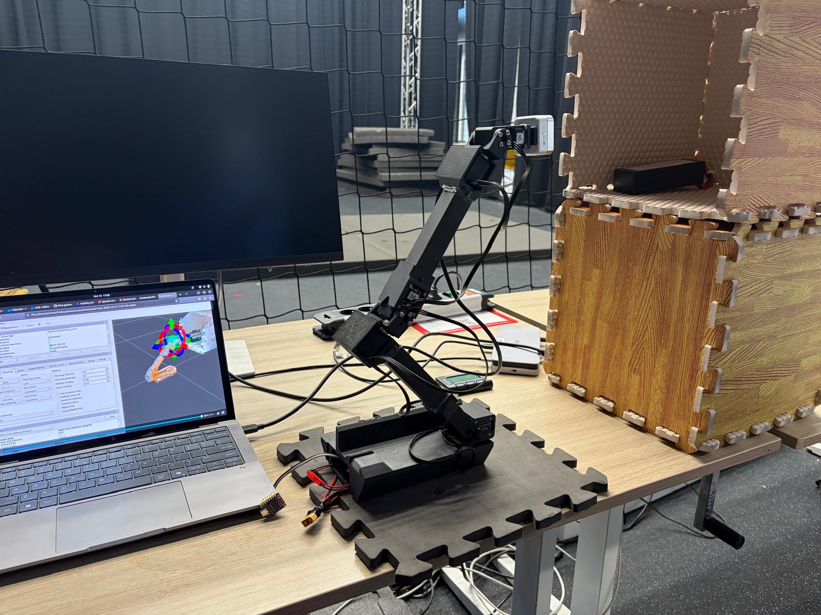
The result is a click-to-inspect workflow. The operator sees the live point cloud of a depth camera mounted on the arm's wrist and clicks the surface of interest. The software estimates the local surface, chooses a camera position in front of it, plans a collision-free motion and shows it to the operator. The arm moves only after the operator confirms.
The arm itself is built from off-the-shelf parts: six smart bus servos (Feetech ST3215) and two linear actuators, driven by an ESP32-C3 microcontroller, with an Intel RealSense D405 depth camera in the hand. Everything above the microcontroller runs in ROS 2 Jazzy and MoveIt 2, packaged in Docker.
How It Works
Surface estimation. The software takes the depth points within 2 cm of the click and fits a plane through them using a singular value decomposition. This gives the surface normal and a flatness score, so clicks on edges or corners are flagged. For about 35,000 points this takes 3 ms.
Choosing a camera pose. Head-on at 10 cm is the preferred view, but it is not always reachable. The software generates candidate camera poses (7 to 12 cm away, up to 40° from head-on, and 12 rotations of the camera about its viewing axis) to increase the chances of finding a feasible solution and ranks them by how close they are to the ideal. It then checks them in order: first reach, then inverse kinematics with collision checking, then path planning. The first candidate that passes all three wins.
Tiered path planning. Each motion is first planned as a straight line in joint space (Pilz PTP), which is fast and gives the same, shortest joint motion every time. Only when that line is blocked does a sampling-based planner (OMPL RRTConnect) search for a way around the obstacle. In the best case a plan is ready in 0.2 s. Obstacles come from the same depth camera, which MoveIt turns into a 3D occupancy map.
Control. Planned trajectories run through ros2_control at 100 Hz and a custom hardware interface, which sends position setpoints over USB to the ESP32-C3. Each servo runs its own position loop and speed ramp, so the interface sends only changed setpoints, limited per joint, and checks accuracy on arrival. Speed and acceleration limits were measured on the real arm. The same interface has three backends: the real arm, a mock arm for testing, and a Gazebo simulation.
Self-collision. The arm's parts sit within a millimetre of each other when it is folded. To tell real contact from near misses, the collision shapes were rebuilt with a finer convex decomposition (CoACD). The results were checked against the exact CAD geometry over thousands of arm poses.
Results
- The full chain, from a click on a surface to the camera positioned in front of it, runs on the real arm.
- The same software runs unchanged in Gazebo, on a mock arm and on the real hardware.